A Practical Guide from Simple Interfaces to Digital Twins
Introduction
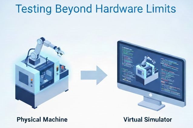
Many machine manufacturers consider building a simulator for their systems. The motivation is clear: being able to test behavior before the first machine is assembled, and enabling other teams to validate applications without relying on physical hardware.
But once you decide to build a simulator, a fundamental question appears:
What architecture should you use?
There is no single answer. In practice, several approaches exist, each with different trade-offs in complexity, maintainability, realism, and development effort.
This article consolidates a full series exploring the main PLC simulator architectures—from the simplest interface-based solutions to fully physics-based environments.
1. The Spectrum of PLC Simulation Architectures
Before diving into each approach, it’s useful to understand the full landscape:
- Simulator independent from the final code
- Simulator embedded inside the production code
- Simulator outside the production code, same platform, same project
- Simulator outside the production code, same platform, different project
- Simulator on a different platform, connected through communications
- Simulator on a different platform, connected through communications + 3D environment
Each of these solves a different problem. In many real-world systems, combinations of these approaches are used.
2. Simulator Independent of the Final Code
This approach is especially useful when multiple teams are working on interconnected systems.
The goal is simple:
Enable development and testing even when the real counterpart is not available.
Instead of simulating full machine behavior, the simulator focuses on:
- Communication interfaces
- Handshaking logic
- Minimal internal states
Advantages
- Fast to implement
- Low development effort
- Helps unblock teams (SCADA, software, integration)
- Enables early validation of interfaces
Limitations
- Errors in the simulator can affect test results
- Often abandoned once real hardware is available
- Difficult to scale for complex systems without internal logic
This approach is highly effective—as long as it is clearly understood that it is not a full simulation, but an interface-level tool.
3. Simulator Inside the Production Code
In this architecture, simulation logic is implemented directly within the PLC program.
While unit testing can often be achieved through structured logic (functions, function blocks), integration testing requires simulation—and this is one way to achieve it quickly.
However, this approach comes with a fundamental issue:
Simulation and production logic become mixed.
A typical symptom is the presence of conditions like:
IF machine_in_simulation THEN …
Advantages
- Very fast to implement
- Useful for proofs of concept
- Enables early demonstrations
Limitations
- Breaks clean architecture principles
- Simulation code may run in production
- Increases system complexity and risk
- Hard to maintain long term
This approach can be useful temporarily, but it should never be the target architecture.
4. Simulator Outside the Production Code
Same Platform, Same Project
This is one of the most balanced and practical approaches.
Production and simulation logic are separated into different programs within the same project. During simulation, both run together. In production, only the real control logic is executed.
Advantages
- Simulation code never runs in production
- Clear separation of responsibilities
- Supports structured integration testing
- Each control unit can have its own simulator
- Direct access to internal variables when needed
Limitations
- Requires proper architectural design
- Simulator bugs can mask real issues
This approach provides a strong balance between:
- Maintainability
- Testability
- Safety
It is particularly well suited for medium to large systems.
5. Simulator Outside the Production Code
Same Platform, Different Project
Here, the separation goes one step further.
The simulator is implemented as a completely independent project, even though it runs on the same platform.
This ensures a clean production environment, but shifts complexity into communication design.
Advantages
- Production code remains completely clean
- Simulation logic is fully isolated
- Flexible structure per control unit
Limitations
- Requires a well-defined communication interface
- No direct access to internal variables
- Risk of unintended access if interfaces are not properly controlled
In this architecture, the interface becomes the system. Its design is critical.
6. Simulator on a Different Platform (Communication-Based)
In this model, the simulator runs on a completely different platform and communicates with the PLC.
This is particularly suitable when:
- Inputs are already communication-based
- A configuration layer can abstract real vs simulated inputs
A common implementation includes:
- A mapping layer in the PLC
- Conditional assignment of inputs (simulation vs production)
Advantages
- Very clean production code
- High flexibility in simulator implementation
- Technology independence
Example setups:
- PLC running on Siemens
- Simulator built with another PLC platform or a C# application
Limitations
- No access to internal variables
- Communication latency and synchronization challenges
- Some integration tests become more complex
This approach introduces a key trade-off:
clean architecture vs observability and control.
7. Simulator with 3D Environment and Physics Engine
This is the most advanced and complete approach.
The simulation runs inside a physics engine, where system components are modeled with realistic behavior. The PLC interacts with this environment through industrial communication protocols such as:
- EtherNet/IP
- Modbus TCP
- OPC UA
The result is a system where behavior is driven not only by logic, but by physical simulation.
Advantages
- High realism
- Enables process validation and optimization
- Foundation for digital twins
- Supports advanced use cases beyond testing
Limitations
- High modeling effort
- Synchronization complexity
- Dependency on communication performance
This approach is not just about validation anymore.
It becomes a strategic tool for engineering, especially when moving toward full digital twin implementations.
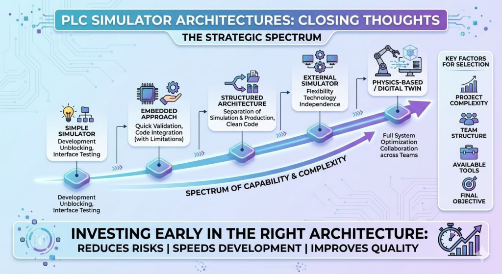
8. Choosing the Right Architecture
There is no universally “best” solution.
The right choice depends on:
- Project complexity
- Team structure
- Available tools and platforms
- Simulation objectives
A simplified view of the spectrum:
- Interface simulators → unblock development
- Embedded simulation → quick validation (temporary)
- Structured architectures → clean and scalable systems
- External simulators → flexibility and independence
- Physics-based environments → optimization and digital twins
9. Final Thoughts
As systems grow in complexity, simulation is no longer optional.
It evolves from:
- A support tool
- A core engineering capability
Used correctly, simulation enables:
- Earlier validation
- Faster development cycles
- Better collaboration between teams
- Reduced commissioning risks
But the key is not choosing the most advanced solution.
It is choosing the right architecture for your context.
Investing in simulation architecture early has a direct impact on:
- System quality
- Development speed
- Long-term maintainability
And in many cases, it is the difference between a simulation that is used—and one that is abandoned.